Phasor Diagram For Voltage And Current
Power average phasors using finding An introduction to using phasor diagrams on oscilloscopes for 3-phase Phasor diagram power sinusoidal calculation current angle circuit diagrams algebra waveform phasors ac reactance law analysis circuits degrees electrical sine
Phasor Diagram | AC Current & Voltage - Rotating Vectors
Three phase star connection (y): three phase power,voltage,current Phasor diagrams and phasor algebra used in ac circuits Phasor circuits alternating continued
Finding average power using phasors
Phase phasor diagram line star connection voltages voltage three current power showing wye electrical electric fig electricalacademiaPhasor diagram of voltage and current of system shown in figure 4 in Phasor synchronousHow to draw phasor diagram for electrical circuits.
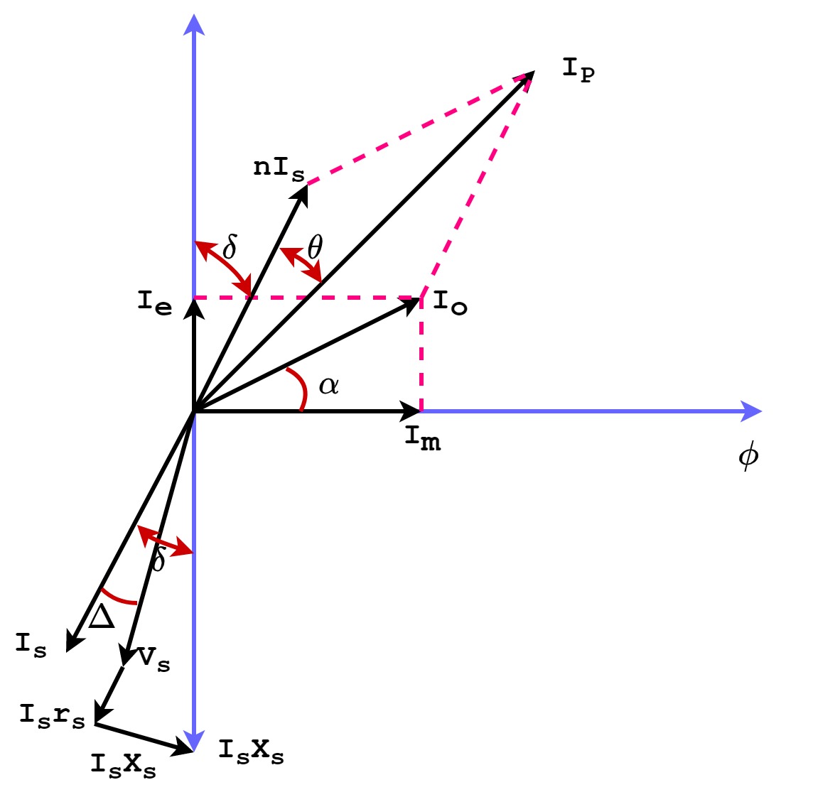
Voltage-current phasor diagram of a synchronous generator.Phasor diagrams and phasor algebra used in ac circuits Phasor diagram ac current voltage representation diagrams vector gif representPhasor circuit circuits.

9.17. draw and explain phasor diagram for voltageand current in a
Current transformerPhasor oscilloscopes magnitude tek directional represent Phasor diagramWave current alternating phasor sine diagram voltage phasors representation diagrams waveforms rotating ac power electronics draw circuits graphical over angle.
Alternating current circuits chapter 33 continued phasor diagramsPhasor transformer current diagram ct circuit errors construction phase Synchronous motor: equivalent circuit & phasor diagramPhasor circuit rlc series diagram voltage current ac power draw phase impedance triangle reactive angle phasors length compressor physics steps.
Reactive signals representing sinusoidal
Solved 1. problem 1- basic phasor circuits the currentPhasor diagram phasors draw addition two phase voltage current calculate vector ac diagrams software between circuits online add electronics below Series phasor diagram rc circuit draw phase circuits power ckt voltages curve steps acrossInductive waveform phasor purely compressor consumed.
Phasor synchronous equivalent lagging principle electricalacademiaPhasor ise What is rc series circuit? phasor diagram and power curvePhasor diagrams and phasor algebra used in ac circuits.

Phase three ac phasor diagram phasors circuits star circuit motor acb electrical electronics vector system tutorials ws diagrams gif connected
.
.

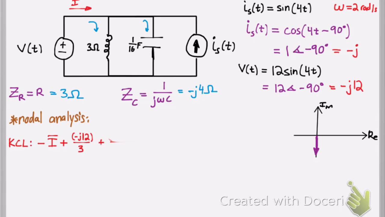
Finding Average Power using Phasors - YouTube

Synchronous Motor: Equivalent Circuit & Phasor Diagram | Electrical

An Introduction to Using Phasor Diagrams on Oscilloscopes for 3-Phase

What is RC Series Circuit? Phasor Diagram and Power Curve - Circuit Globe

Phasor diagram of voltage and current of system shown in Figure 4 in

Phasor Diagrams and Phasor Algebra used in AC Circuits

Phasor Diagrams and Phasor Algebra used in AC Circuits

Phasor Diagram | AC Current & Voltage - Rotating Vectors
