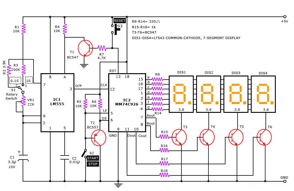
Digital Clock Circuit Diagram Logic Gates
Logic diagramz Digital clock circuit simulation Circuit timer digital diagram ic stopwatch stop projects counter segment display schematic lm555 using simple electronics led circuits electronic digit
Xor Logic Gate Circuit Diagram : 1 - The output is 'low' if both the
Logic gates circuits digital truth table gate part small blocks building verification versatile why volts nuts other nutsvolts Clock circuit digital using simulation hrs dld ic counter Xor logic gate circuit diagram : 1
Clock digital logisim logic diagram implement bcd electrical fpga simulate
Digital alarm clock using 4026 logic gates schematic circuit diagramDigital stop watch Nand xor logic nor xnor vhdl wiring simulate verify circuits scosche input inputs cktSmall logic gates — the building blocks of versatile digital circuits.
.


Xor Logic Gate Circuit Diagram : 1 - The output is 'low' if both the

Small Logic Gates — The building blocks of versatile digital circuits

Digital Clock Circuit Simulation - YouTube

fpga - How can I implement a digital clock in Logisim? - Electrical

Digital Stop Watch - Simple Projects
