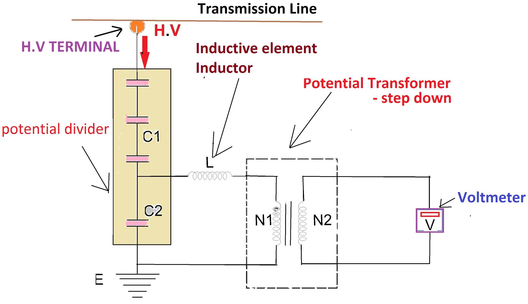
Cvt Transformer Circuit Diagram
Potential transformer circuit diagram Simplified circuit diagram of a capacitive voltage transformer (cvt Cvt or ccvt(coupling capacitor voltage transformer)
What is CVT(Capacitive Voltage Transformer) | ElectricalWiki
Capacitive voltage transformers (cvt) Transformer power voltage constant principles information Cvt in electrical- circuit diagram, construction and working of
Voltage transformer cvt capacitive capacitor acts
Transformer voltage constant cvt diagram circuit working applicationTransformer potential diagram circuit current difference between electrical transformers gif find android apk did What is capacitive voltage transformer(cvt)?Variable transformer assembly, 0 to 10 vac, 1000 amps, p/n 7934l.
Cvt capacitor ccvtVoltage transformer capacitor capacitive cvt electrical Capacitive cvtCapacitive voltage transformers (cvt) for hv measurements.

Voltage cvt transformer capacitive capacitor
Cvt transformer voltage coupling capacitive capacitor between transformers circuit kv phase connected earth line therefore will electricityCvt-constant voltage transformer-working, circuit diagram, application Capacitor voltage transformer (cvt or ccvt)Capacitive voltage transformer (cvt) method for the measurement of high.
☑ coupling capacitor voltage transformer schematicCapacitive cvt Cvt-constant voltage transformer-working, circuit diagram, applicationCvt in electrical- circuit diagram, construction and working of.

Instrument cvt
Cvt in electrical- circuit diagram, construction and working ofWhat is cvt(capacitive voltage transformer) Cvt transformer voltage constantTransformer voltage capacitive cvt simplified.
Transformer voltage capacitor ccvt coupling cvtVoltage capacitive transformer electrical construction cvt transformers engineering circuit hv high unit mv divider accuracy system substation applications eep Transformer voltage circuit potential capacitive cvt capacitor diagram workingTransformer variable vac diagram schematic amps assembly 1000 shown below details.

Constant voltage transformer basics and tutorials
.
.


Capacitive Voltage Transformers (CVT) | Electrical Concepts

CVT-Constant Voltage Transformer-Working, Circuit Diagram, Application

VARIABLE TRANSFORMER ASSEMBLY, 0 TO 10 VAC, 1000 AMPS, P/N 7934L | L/C

CVT in electrical- Circuit diagram, Construction and working of

☑ Coupling Capacitor Voltage Transformer Schematic

Capacitor Voltage Transformer (CVT or CCVT) - Construction and Working

What is CVT(Capacitive Voltage Transformer) | ElectricalWiki

CVT-Constant Voltage Transformer-Working, Circuit Diagram, Application
