Current Source Inverter Circuit Diagram
Electrical video library: v/f control of induction motor Medium power inverter circuit diagram Inverter controller
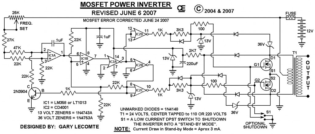
6 Best – Simple Inverter Circuit Diagrams – DIY Electronics Projects
Current source inverter circuit diagram Block diagram of the current source inverter controller. Inverter circuitry
2000w inverter circuit diagram
Inverter as high voltage low current source circuit diagramInverter voltage circuit source diagram motor induction control figure frequency variable Inverter conduction inverters switching sine circuitdigestInverter circuit 2000w diagram power high circuitspedia resolution click.
12 volt 1000 watt power inverter design processInverter circuit diagram power 1000w wiring 12v 220v schematic npower watt dc 500w mosfet ac 110v wave circuits inverters sine Inverter three(pdf) manual for solar technician.

Inverter current source circuit diagram power seekic filtering exists reactive capacitive absorption load role features
Inverter diagram circuit 24v 2kva watt build 2000 electrical simple schematics transformer board schematic power wiring dc ac electronic useCircuit diagram of load resonant current source inverter for induction Inverter voltage high current low source circuit diagram 555 timer power schematics circuits ic using electronic12+ 3 phase inverter circuit diagram.
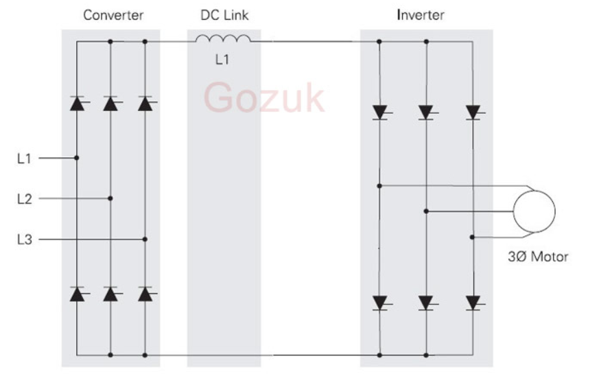
Electrical video library: v/f control of induction motorScheme of a three-phase current source inverter Inverter circuit diagram 1000w power spwm 12v watt dc 1000 process board volt inverters driven sourceSingle phase half bridge inverter explained.
How to build a 2kva inverter circuit diagram : 2000 watt inverter
Inverter current circuit source diagram figureInverter circuit power diagram medium gr next supply cd4069 cmos circuits Inverter resonant6 best – simple inverter circuit diagrams – diy electronics projects.
Inverter fig5Inverter mosfet circuits diagrams (a) voltage source inverter configuration; (b) current source inverterWhat is current source inverter? definition, control & closed loop.

Current inverter source motor induction drive fed control circuit controlled operation dc link closed
1000w power inverter circuit diagram1, three phase inverter circuit .
.


(a) voltage source inverter configuration; (b) current source inverter

Current source inverter circuit diagram - Power_Supply_Circuit

6 Best – Simple Inverter Circuit Diagrams – DIY Electronics Projects

What is Current Source Inverter? Definition, Control & Closed Loop

ELECTRICAL VIDEO LIBRARY: v/f control of induction motor
ELECTRICAL VIDEO LIBRARY: v/f control of induction motor

Inverter as High Voltage low Current Source Circuit Diagram

Block diagram of the current source inverter controller. | Download
